


“Origins of the West African Launcher from TCG Files” by Andy Presby
CONTAINS PROPRIETARY INFORMATION OF THE TENNESSEE VALLEY INTERSTELLAR CONGLOMERATE
— TCG INTERNAL USE ONLY —
ALL PATENTS PENDING
Form TCG1116-B: Annual TCG Employee Crazy Idea Competition
Proposal #: 3214
Proposer: Omer Ehrlich, Intern
Current Management Rotation: Oral Hygiene Products
To: John-Philip Jeffy, CEO TCG
Title: REDUCED COST SPACE LAUNCH SYSTEM
Benefit of Proposal: The space between the Earth and Moon is filled with a variety of spacecraft performing many functions vital to modern society. The sheer number of spacecraft, the range of orbits they cover, and the diversity of their activities have outpaced predictions of even the most optimistic of space enthusiasts from before the Second Space Race. This abundance challenges the space industry’s capability to resupply, repair and provide other services to in-orbit customers. While large reusable heavy lift rockets have provided the most economic way to move high volume payloads to orbit for a generation or more, that delivery method is suboptimal for multiple point orbital deliveries. This proposal identifies a new system capable of reliable repeatable launch of payloads up to one ton into any Earth-centered orbit on-demand to meet this need and propel TCG to the forefront of this emerging market segment.
Motivation for Idea: If we can do this more cheaply, we can make a lot money. Or, we could offer the transport for much less and make a lot more orbital industry economically viable.
Getting material into space inexpensively has long been the goal of the space industry. “Once you get your ship to orbit you’re halfway to anywhere” has been a truism of space travel since the 20th century. It remains true today. The essential problem of getting off the Earth is a matter of throwing something high enough and fast enough that when it falls back down, it overshoots the Earth. See Diagram One below.
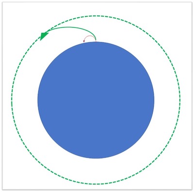
Diagram One: Getting to Orbit
The hard part is “throwing” your spacecraft that fast. An object in stable orbit around the Earth goes anywhere from eight to ten kilometers per second (km/s) depending on the height and shape of the orbit. That is in an ideal world with no air friction and where we instantly teleport our spacecraft to the right height at the right speed. In the real world, other influences make our vehicle lose speed and make getting into orbit harder.
These are primarily:
- Gravity losses as the Earth’s gravity pulls on the vehicle the whole way up
- Air drag for the portion of the flight that goes through the atmosphere. (It is important to note that the densest part of the atmosphere is down at sea level, and total losses due to air drag drop off as we start our trip to space from higher altitudes.)
- Any other maneuvers needed to get into the orbit we want
These losses add up and mean that getting to orbit actually means being able to go 9 to 12.5 km/s.
The other thing that makes getting to space hard is the fact that we still use rockets to do it. Rockets have to carry everything with them that they need on their trip. This includes all their fuel and the oxygen needed to burn that fuel. A given rocket carrying a given amount of payload with a given amount of fuel and oxygen can get to a given speed by burning all of it. That speed is called the rocket’s “velocity increment” or “delta vee.” If we want to go faster with that rocket pretty much all we can do is carry more fuel and oxidizer to go with it. This however buys us into diminishing returns, because every kilogram of fuel and oxidizer we add increases our gravity losses and makes that new propellant less effective at giving us more speed.
Looking at this we see a few places where we might be able to make a space launch using rockets easier. The first is that we could launch from as close to the equator as possible. This would give us an extra boost of speed from the Earth’s rotation. This is why many nations try to build their space launch complexes as close to the equator as possible, and some companies still launch from ships at sea or airplanes that fly down to the equator. The next would be to launch as high up in the atmosphere as we could to reduce air drag. The third would be to keep your vehicle as light as possible. A way to convert air into fuel or oxidizer on the way up thru the atmosphere would help. Any way to add speed to the vehicle that didn’t require it to carry more fuel would also be a great help.
Proposal Overview: It turns out that there is a way to do all of the things above and this proposal submits this method in accordance with Reference 1. It was first proposed in the latter half of the 20th century, as many good aerospace ideas seem to have been. A number of authors thought of the idea of using a magnetic levitation rail up the side of a mountain to assist an airbreathing, rocket-propelled vehicle in achieving orbit. [See Reference 2 below. Legal review pending on TCG acquisition of any needed IP.] A sled on the rail carries the vehicle, and lets it go as high as possible to reduce the amount of air drag. Further reductions in air drag could be realized by enclosing the rail in a large tube and evacuating air from it. The speed that the rail imparts to the vehicle will allow it to start its engines and proceed to orbit after release. The fact that the rail, sled, and (most importantly) their big and heavy electrical generators are left on the ground means that the vehicle can get its first kilometer per second or two of speed effectively “free” which will significantly increase the amount of payload a given vehicle can loft.
Military missiles, aircraft, and even some launch vehicles have integrated hypersonic technology. The following sections describe each component in more detail. Please see Diagram Two for an overview.
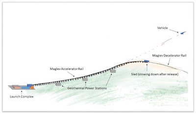
Diagram Two: System Overview
Maglev Rail and Sled (“Launcher” and “Sled”): The magnetic levitation (maglev) rail and its associated sled are the parts of the system that stay on the ground. Their job, as stated above, is to impart as much velocity as possible to the vehicle in order save fuel and increase delivered payload mass to orbit. The site of the launcher requires a tall (>2000 meters) mountain formation, good local power infrastructure, and access to multi-modal transportation options to enable payload transportation and transshipment of goods returned from orbit. Access to nearby airport facilities is desirable to allow returning launch vehicles to land at the launch facility for transportation cost savings. Access to other air traffic facilities down range from the launcher is also helpful to provide abort options in case of failures on launch. It would be ideal to identify locations near the equator to reduce the amount of fuel that vehicles must burn reaching the equator and maximize payload to orbit under ideal conditions.
The launcher takes the form of a linear accelerating rail likely ten or more kilometers long built up the side of the selected mountain. Control, vehicle maintenance, payload processing, and office facilities are located at one end of the rail where ready vehicles can be placed on it. The rail must smoothly run up the mountainside with a minimum curvature and no “bumps” to reduce the lateral forces and shocks that a vehicle experiences during launch. It will likely be necessary to elevate the rail above the ground for this reason. The rail should be partially or fully enclosed to minimize environmental wear on associated power handling equipment. Farther up the launch path, where vehicles would be going faster, it would be beneficial to fully enclose the rail and include a pumping system to reduce air pressure and thus drag. This enclosure could be above or below ground.
The interface between the rail and the launch vehicle would be a sled capable of being levitated and accelerated by the magnetic levitation rail, while holding the launch vehicle in place, surviving the forces involved for the roughly 20-30 seconds a typical launch would entail, releasing the vehicle safely at the correct time, and then being slowed down by the rail for return to the processing facility and reuse. These requirements are novel but conceivable as scaled up application of the technology in electromagnetic catapult “shuttles” used today on aircraft carriers. It should be noted that the rail does not end at the release point but needs a “decelerator’” section necessary to slow down the sled for retrieval. This section can be much shorter (perhaps 1 to 2 kilometers long) because the sled can presumably be built to withstand larger forces than the launch vehicle. Thus it can be slowed down more rapidly than the whole assembly was first accelerated.
One of the reasons that a maglev-assisted space launch system has not been built on Earth to date is that this concept was first proposed when magnetic levitation and electromagnetic catapults were in their infancy. The raw speed of the sled at the point of vehicle release (1-2 kilometers per second) was difficult to envision at the time. Not only that: the required engineering work to make the rail and sled survive that repeated use reliably, day in and day out, for maybe dozens of launches a day, for years at a time had not been done. Today, however, high-speed electromagnetic catapults are routinely used in naval systems and longer higher speed units are coming online for lunar bases. Reliable magnetic levitation mass ground transit, though still a niche application, is much more common and has operated safely for decades. It is true that no one has built one of these up the side of a mountain yet, but the civil engineering of this system is within our reach.
Highly Reusable Airbreathing Aerodynamic Hypersonic Launch Vehicle (“Vehicle”): The vehicle is at least as significant an advance over the current state of the art as the rail. The integration of hybrid hypersonic engines into a reusable winged aerospacecraft means that the vehicle, once lofted, can economically fly to the equator to get the maximum benefit from the Earth’s rotation. It can also maneuver using its airfoils and airbreathing engines to achieve any desired orbit most economically. Finally, its airfoils and airbreathing propulsion allow return to a conventional landing strip near the launcher after re-entry using minimum fuel. This offers a flexibility unparalleled by the large conventional reusable pure-rocket vehicles that currently dominate the up-mass service market.
The airbreathing aerodynamic reusable hypersonic launch vehicle takes advantage of several technologies that were immature or only conceptual at the time this idea was first proposed. But the payoff will be worth it:
- Carbon composites: Advances allow reliable integrated cryogenic storage tanks for use of the most mass efficient propellant combination available (hydrogen and oxygen) while retaining the strength needed to survive launch, atmospheric flight, reentry, and landing loads reliably and repeatedly.
- Additive manufacturing: Advances in industrial fabrication techniques make integrating denser metal structural elements and heat management technologies into carbon composite airframes feasible.
- Boundary layer manipulation: Our current understanding of plasma physics makes it possible to manipulate boundary layers to further reduce shock and drag while enhancing thrust.
- Hypersonic propulsion: The perfection of the shock induced combustion ramjet (shcramjet) [3] permits reliable hypersonic flight above Mach 12. Rocket-based combined cycle modifications allow the same hardware to act as a rocket in space. Magnetohydrodynamic kinetic energy bypass technology permits the use of highly reliable supersonic turbojets under hypersonic conditions and even extraction of electrical power from the airflow [4]. These advances all enable a small number of engines to operate all the way from sea level to space.
- Integrated oxygen liquification: Advances in Stirling engines and oxygen separation and liquification techniques allow the vehicle to top off its oxidizer tanks while “cruising” the launch site. This maximizes payload to orbit.
This flexibility, of course, comes with a cost: complexity. As in all launch vehicles, every gram of mass will need to contribute the maximum possible benefit to the system as a whole. The propellants won’t just be used to make the vehicle go but will need to help cool the leading edges of the nose and the wings. Structural spars and skin surfaces won’t just hold everything together but will also contain heat pipes to also help keep the vehicle cool. Boundary layer manipulation and clever use of the engine MHD bypasses may allow the vehicle to perform some maneuvers without moving vulnerable control surfaces in hypersonic airflow. Putting all of the above technologies together will be a challenge . . . but one fit for modern aerospace engineers.
Powering the System: The maglev launcher will draw a substantial amount of power to accelerate the vehicle and slow down the sled. This power can be drawn from the local grid if the site is in an area with adequate power infrastructure. However high power electrical grids with large capacity (gigajoule-scale) pulsed power storage facilities spaced along the rail will be necessary to achieve useful launch speeds. Even more power is demanded if we wish to produce our hydrogen on-site using either electrolysis or methane pyrolysis.
One of the difficulties with these kinds of electromagnetically-assisted launch systems has always been that they are best built up the sides of naturally occurring mountains. These do not tend to have the needed power infrastructure nearby. Furthermore, the kind of pulsed power required for launcher operation is difficult to transport long distances in wires from places where the power infrastructure might be more robust. Simply running large new power lines from dedicated pre-existing power plants is unlikely to be economical. Dedicated local power infrastructure will therefore be needed.
Wind and solar, while often more available in mountainous terrain, also often require the clearance of large amounts of local ecology to get the amount of power needed. The high power levels required by the launcher exacerbate the traditional weakness of these sources: intermittency. Energy storage for a single launch is already large and expensive. Power storage for multiple launches at night or when the wind is calm becomes prohibitive. Fossil fuel powerplants still face substantial investor bias in the West and the fact is that fuel prices have been steadily increasing over the last century. The easiest solution is generally small modular nuclear fission reactors, but these facilities, while safe and reliable, remain expensive today. They will work but another alternative would be desirable.
Geothermal technology may provide the answer. This technology is centuries old. Pockets of heat underground can be used to drive electrical generators. Modern geo-thermal techniques were pioneered in North America and Iceland. It involves digging deep wells to reach pockets of hot rock followed by directional drilling to embed closed loop piping systems with a working fluid in them that runs through the rock to pick up heat and carry it to turbines on the surface. The temperatures in these pockets are upwards of 500°C and can provide renewable power at a density comparable to fossil or fission power plants and far in excess of what solar or wind could do on the same amount of land. The best thing about this for our purposes is that many mountain ranges sit near large natural geothermal power systems. Indeed volcanic mountain ranges contain undreamed of reserves of such power. Microtremors associated with active volcanic regions would complicate the launch system. Adaptions for that might be possible but are beyond the scope of this proposal. Thankfully a dormant, very tall, near equatorial volcano has recently been purchased by the TCG recreations division: Mount Kilimanjaro.
Conclusions: The time is right to do what our predecessors could not and combine these technologies into a launch system to meet the needs of our burgeoning space economy. I hope Mr. Jeffy finds this proposal suitable for funding and further research.
References:
[1] Fabrice Tchami. "Guidelines for Management Track Internship Idea Proposals," TCG Internal Drive.
[2] John Mankins. "The MagLifter—An advanced concept using electromagnetic propulsion in reducing the cost of space," AIAA 1994-2726. 30th Joint Propulsion Conference and Exhibit. June 1994.
[3] Couture, Dominic & Dechamplain, Alain & Stowe, Robert & Harris, Paul & Halswijk, Wouter & Moerel, Jean-Luc. “Comparison of Scramjet and Shcramjet Propulsion for a Hypersonic Waverider Configuration,” 44th AIAA/ASME/SAE/ASEE Joint Propulsion Conference and Exhibit. 10.2514/6.2008-5171. 2008.
[4] Theresa L. Benyo. (2010). “The Effect Of Magnetohydrodynamic (MHD) Energy Bypass On Specific Thrust For A Supersonic Turbojet Engine,” AIAA-2010-232/NASA-TM-2010-216734, December 2010.
Jeffy: Can we send this kid to a research division?
Chummy: Please, no, boss. The toothpaste guys need this kid.
Jeffy: Fine. But make sure nobody headhunts him away from us.
Chummy: Will do, boss.
Jeffy: What about setting up some kind of research retreat space at Kilimanjaro though? The site is gorgeous.
Chummy: I'll make that happen too, boss.
Copyright © 2022 Andy Presby
Andy Presby is a former U.S. Navy nuclear submarine officer and current aerospace engineer with degrees in space systems engineering, astronautics, and physics. This fictional-non-fiction article is set in the world of Joelle Presby’s The Dabare Snake Launcher. Joelle is a former U.S. Navy nuclear engineering officer, a former business consultant, and current spouse to Andy Presby.